

Introduction
An expanded look at Internet usage over the last couple of decades shows a multifold boom in the average internet speed experienced by a user. The internet is faster than ever, with a lower-bound of 1 Mbps and averaging 10 Mbps+ across most regions. And, not just the speed, the remarkable adoption of the internet for a widespread userbase has increased to nearly 60% of the total world population.
There has been a clear lack of optimization and customization in the delivery of video streams in the past. The focus was to deliver them over limited bandwidth, thus manipulating streams at the server side. This would often lead to unpredictable server costs for the video conferencing provider.
The growing network of broadband connections, paired with the arrival of 4G and now 5G services, has provided a unique opportunity to look beyond the bandwidth savings model for video conferencing, and rather focus on optimizing the cost of media delivery through intelligent systems over standard configurations.
At Sariska, our focus has been to build products for the future. Internet bandwidth constraints would be a thing of the past, if they aren’t already. This blog digs deeper into the motivation behind building our media delivery services on top of the Jitsi video conferencing stack, and argues why this approach is radically new and future-proof.
P2P: Problem Overview
Let’s start with the simple case of a 1:1 video calling solution, developed without the need for a media server. Peers can connect and disconnect from the network at any time, and they can share resources with other peers on the network.
In a P2P network, each peer is equal and can connect to any other peer on the network. In order for two peers to communicate, they first need to find each other on the network. To do this, each peer broadcasts a message that contains its own IP address. Other peers on the network can then reply with their own IP addresses, allowing the two peers to establish a connection.
Disadvantages of Peer-to-Peer over Media Servers
P2P connections are simple, easy to setup and cost almost nothing. But, once the number of peers starts to grow beyond 3 or 4, the P2P network or mesh begins to be more and more complicated. Since each peer is communicating with every other peer, the following complications arise:
- P2P connections can get unstable and slow.
- As the number of participants grows, the bandwidth consumption and CPU usage increase drastically.
P2P is the least efficient in terms of bandwidth and CPU usage. Hence, to create a video conferencing infrastructure, the choice of a media server comes into play.
Choosing the right Media Server
When it comes to media servers, there are essentially two choices.
MCU (Multipoint Control Units)
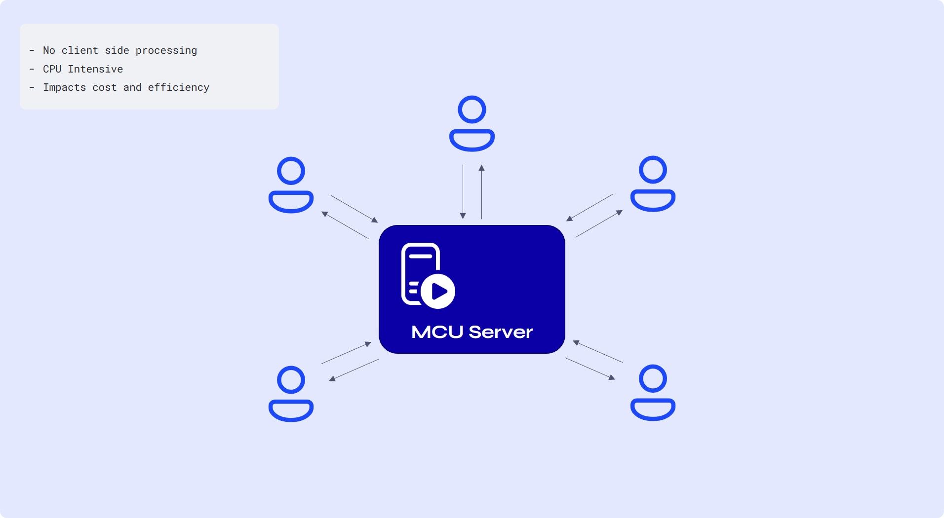
- MCUs are also referred to as Multipoint Conferencing Units. Each peer sends their video and audio streams to the MCU server, which composites all the streams from all the peers, and sends exactly one set of audio and video streams back to each peer.
- This decreases the amount of processing that needs to be done on the client side.
- On the server side, though, this means increased and often unpredictable costs.
- So, as your calls and applications grow, you will need bigger servers in an MCU-based architecture.
- If you are not developing legacy machines, this approach does not take you very far in terms of cost and efficiency.
SFU (Selective Forwarding Unit)
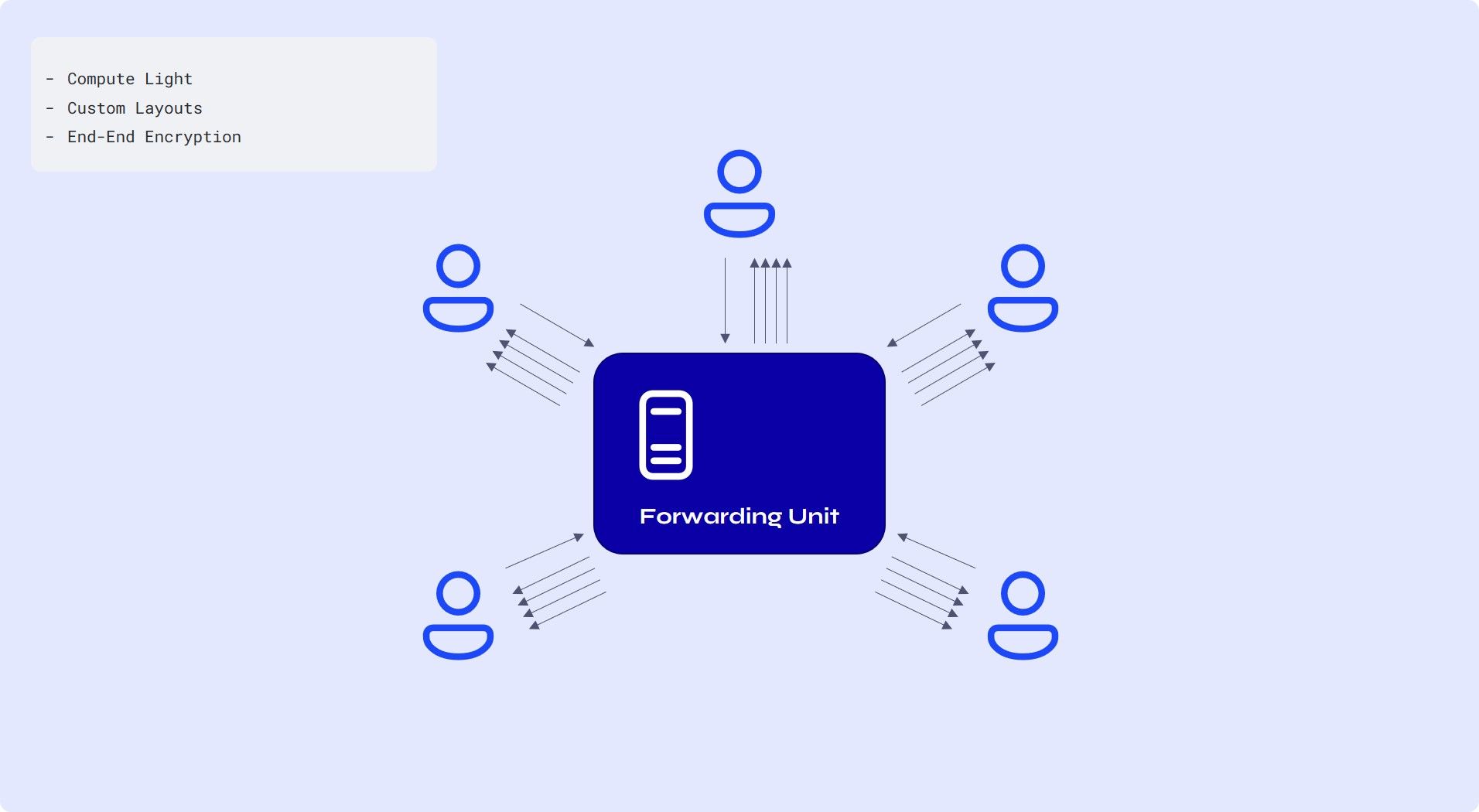
- Each participant still sends just one set of video and audio up to the SFU, like MCU. However, the SFU doesn’t make any composite streams. Rather, it sends a different stream down for each user, essentially working as a relayer rather than a mixer.
- Server side cost greatly decreases for an SFU as compared to an MCU
- This allows participants to have different video layouts since a participant gets multiple streams.
- End-to-end encryption : Because an SFU doesn’t need to manipulate your video in the way that an MCU does, that means you could conceivably implement true end-to-end encryption.
Between the two media server solutions, it's clear that SFU is cost effective in multitudes as compared to the unpredictable cost behaviour of an MCU server. Secondly, since legacy machines are, in fact, legacy, there is no place at scale for them in the future. The ability to have predictably low costs and a choice of video layout clearly tilts the scales towards an SFU-based media server.
The choice then comes down to which SFU-based media server to use.
The solution was easier than we thought. We went about looking for an open source SFU based media server and the first one you’d hear about is Jitsi Videobridge.
It is a mature and fully open-source, webRTC compatible SFU with the proven ability to run thousands of video streams from a single server. Not only that, it was the very first open source SFU out there, so a huge community of developers existed to support this project as well.
The rest of this article dives deeper into the Jitsi Videobridge and the optimizations that come with it. Finally, we bring it all together to argue why Sariska’s design decisions for the media delivery server make it a better alternative to legacy media services.
SFU implementation of the Jitsi Videobridge (JVB)
Jitsi Videobridge is a fully open-source and WebRTC-compatible SFU server designed to run thousands of video streams. It has several advanced features, such as RTCP termination, bandwidth estimations, and bandwidth distribution.
RTCP Termination
The endpoints of a group call are "tricked" into believing that they are on a one-on-one call with the JVB. This has the notable desirable property that bad down-link conditions at a particular receiver do not typically affect the sending bitrate of the senders because, from their perspective, there is only one receiver (the JVB) with a presumably good down-link.
Bandwidth Estimation
The JVB implements the Google Congestion Control (GCC) algorithm to estimate the available bandwidth.
GCC comprises two parts: a delay controller and a loss controller. There are two ways to implement the BWE algorithm. One where both the controllers are running on the send-side, and one where the delay-based controller runs on the receive-side and the loss-based controller runs on the send-side.
Send Side Bandwidth Estimation
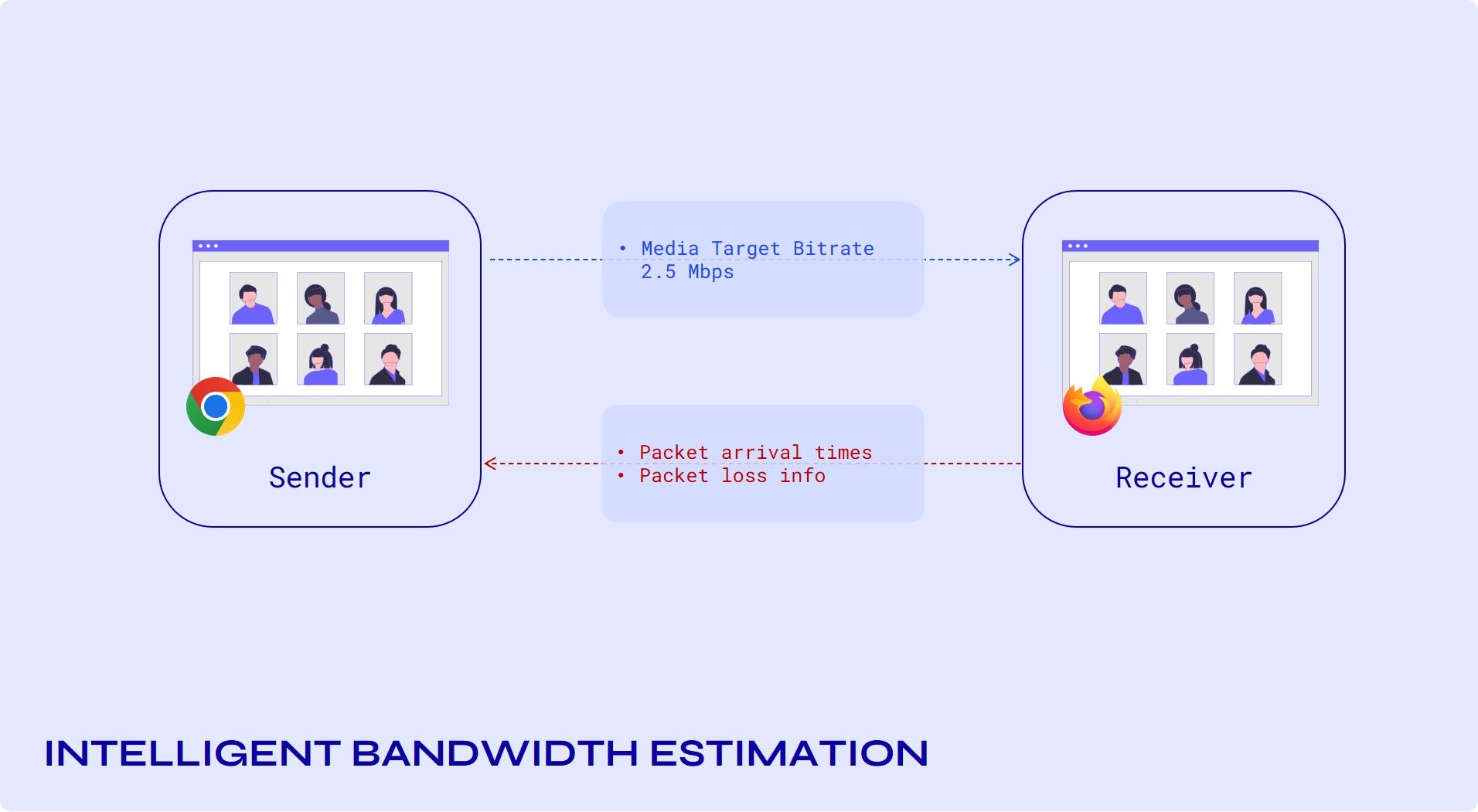
The RTP receiver records the arrival time and the transport-wide sequence number of each received packet, which will be sent back to the sender periodically using the transport-wide feedback message.
The recommended feedback interval is once per frame received or 30ms if it's an audio-only or multi-stream conference. In order to limit the feedback overhead, the interval can be increased to 100 ms.
The sender will map the received sequence number, arrival time pairs to the send-time of each packet covered by the feedback report, and feed those timestamps to the delay-based controller. It will also compute a loss ratio based on the sequence numbers in the feedback message.
Delay-based Controller running on the Receive Side
The second version can be realised by having a delay-based controller at the receive-side, monitoring and processing the arrival time and size of incoming packets.
The sender should use the abs-send-time RTP header extension [abs-send-time] to enable the receiver to compute the inter-group delay variation. The output from the delay-based controller will be a bitrate, which will be sent back to the sender using the REMB feedback message.
The packet loss ratio is sent back via RTCP receiver reports. At the sender, the bitrate in the REMB message and the fraction of packets lost is fed into the loss-based controller, which outputs a final target bitrate. It is recommended to send the REMB message as soon as congestion is detected, and otherwise at least once every second.
The JVB implements send-side bandwidth estimations with a Kalman filter in the delay-based controller.
Bandwidth Distribution
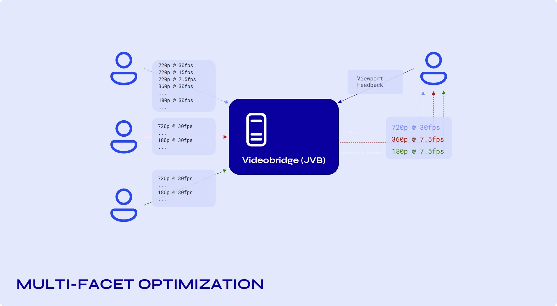
The BitrateController is attached to a destination VideoChannel and it orchestrates the bandwidth adaptability towards its attached endpoint (the endpoint of the attached video channel).
The bitrate controller "reacts" to different events such as endpoints joining or leaving the call, the available bandwidth estimation changing, the active speaker changing, the viewport of a projected source changing, etc.
Simulcast and SVC
Simulcast, in the most simple terms, consists of the simultaneous transmission of multiple versions of a participant’s video stream, which use different resolutions, frame rates, and, most importantly, different bit rates.
With simulcast, encoders produce multiple streams (in the case of a 720p input, they will produce a 720p, 360p, and 180p stream) with different bitrates. The option of multiple streams to the peer means they can easily change video layouts at their endpoints. But, challenges occur when you want to scale, the bandwidth consumption gets high, or otherwise the network might degrade for some users. enters SVC.
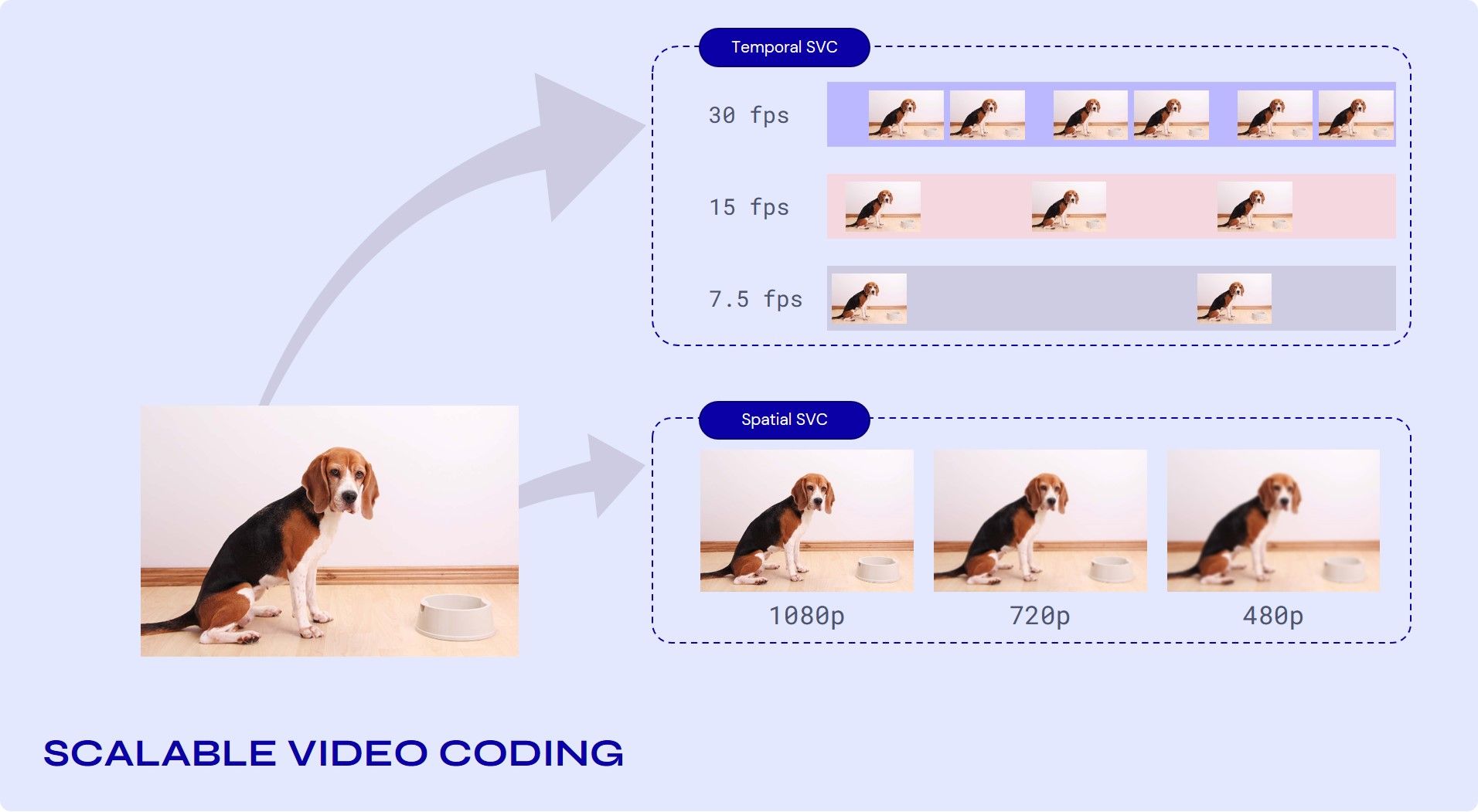
SVC (Scalable Video Coding)
Problems follow scalability, transmission can degrade, or there might be a need for spatial formats, bit rates, or power. To fulfil these requirements, it is beneficial that video be simultaneously transmitted or stored with a variety of spatial or temporal resolutions or qualities, which is the purpose of video bit-stream scalability.
Jitsi uses two forms of scalability to fulfil these needs.
a. Temporal (frame rate) scalability: The motion compensation dependencies are structured so that complete pictures (i.e., their associated packets) can be dropped from the bitstream.
b. Spatial (picture size) scalability: Video is coded at multiple spatial resolutions.
Bandwidth allocation
Bandwidth allocation is the process of selecting the set of layers to forward to a specific endpoint (the "receiver"), or "allocating" the available bandwidth among the available layers. When conditions change, the algorithm is re-run, and the set of forward layers is updated according to the new result.
The overall goal is to provide the most relevant and suitable sets of streams to the receiver, given a limited bandwidth.
The bandwidth allocation algorithm is implemented in BandwidthAllocator.
1. Prioritize
This phase orders the available sources in the desired way. It starts with sources coming from the endpoints ordered by speech activity (dominant speaker, followed by the previous dominant speaker, etc). Then, it moves the sources from the endpoints that are NOT sending video to the bottom of the list.
2. Use Last.
This phase disables the video sources in the list that are not among the first LastN. Note that the effective LastNvalue comes from the number signalled by the client, potentially also limited by the static and dynamic configuration of the bridge.
3. Allocation
The final phase is the actual allocation.
- Initialize the potential layers The first step is to initialise a list of layers to consider for each source. The following is the way the list is prioritized. Those with a higher resolution and frame rate than the constraints The ones which are inactive (the sending endpoint is currently not transmitting them) Layers with high resolution but insufficient frame rate, that is at least the preferred resolution but a frame rate less than the preferred frame rate.
- Allocation loop It starts with no layers selected for any source, and the remaining bandwidth is equal to the total available bandwidth. Until there is remaining bandwidth, it loops over the sources in the order obtained in phase 1, and tries to improve the layer of each.
Geo Location Optimization(SFU cascading or OCTO Protocol)
Cascaded SFUs are two or more SFUs that are interconnected in such a way that allows for one conference to span multiple SFUs.
Simple sharding approaches are easy to scale horizontally; you just point all the users of one conference to a particular server. This approach gets the job done when scaling for users in one geographical area, but latency comes into play when users are located in different parts of the world.
Consider a scenario where one participant is in India while two others are in the USA. Now, if you select a server in India for conferencing, it leads to huge latency between the participants in the US and India, which then also gets worse between the two participants in the US since the stream travels all the way to India and back.
Consider another scenario as shown in the image below.
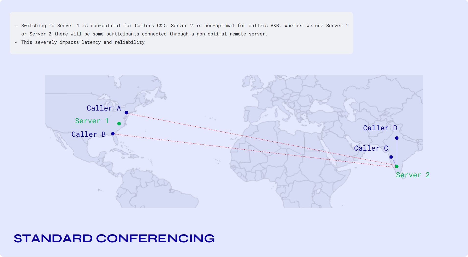
Switching to Server 1 is non-optimal for callers' C&D. Server 2 is non-optimal for callers A and B. Whether we use Server 1 or Server 2, there will be some participants connected through a non-optimal remote server.
The solution is cascading.
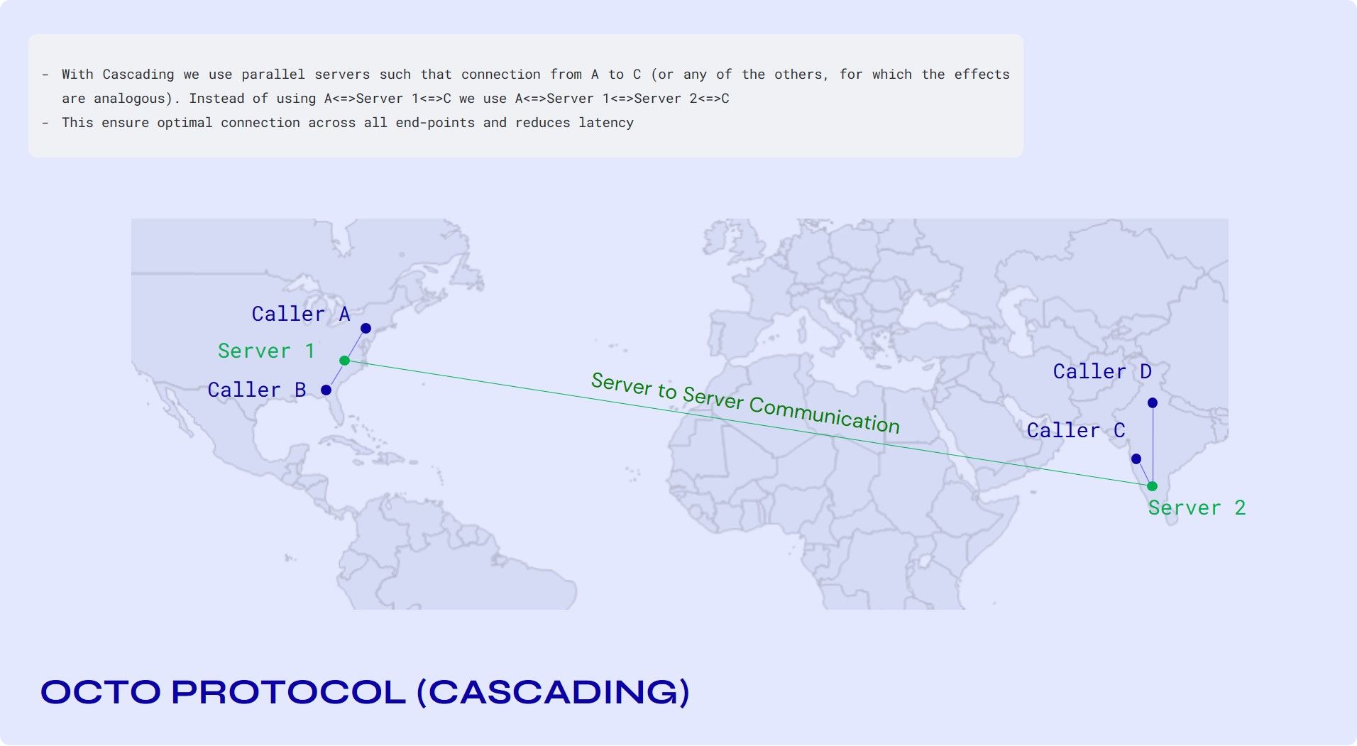
The SFU connection from C to D hasn’t changed—that still goes through Server 2. For the connection between A and B, we use Server 1 instead of Server 2 as in the previous diagram, which is obviously better. The interesting part is actually the connection from A to C (or any of the others, for which the effects are analogous). Instead of using A<=>Server 2<=>C we use A<=>Server 1<=>Server 2<=>C.
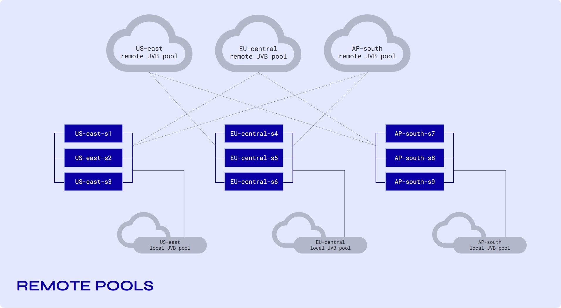
JVBs (Jitsi Videobridges) are not associated with a specific shard. A "shard" now consists of just a signaling node (running jicofo, prosody, and Nginx). We have a few of these per region, depending on the amount of traffic we expect.
We have pools of JVBs, one pool in each region, which automatically scale up and down to match the current requirements.
In addition, we have "remote" pools. These are pools of JVBs that make themselves available to shards in remote regions (but not in their local region). This separation of "local" and "remote" pools is what allows us to scale the infrastructure without the number of cross-connections growing too much.
You can go through this article on webrtchacks.com to find out more about SFU cascading.
Further Optimization using Last N
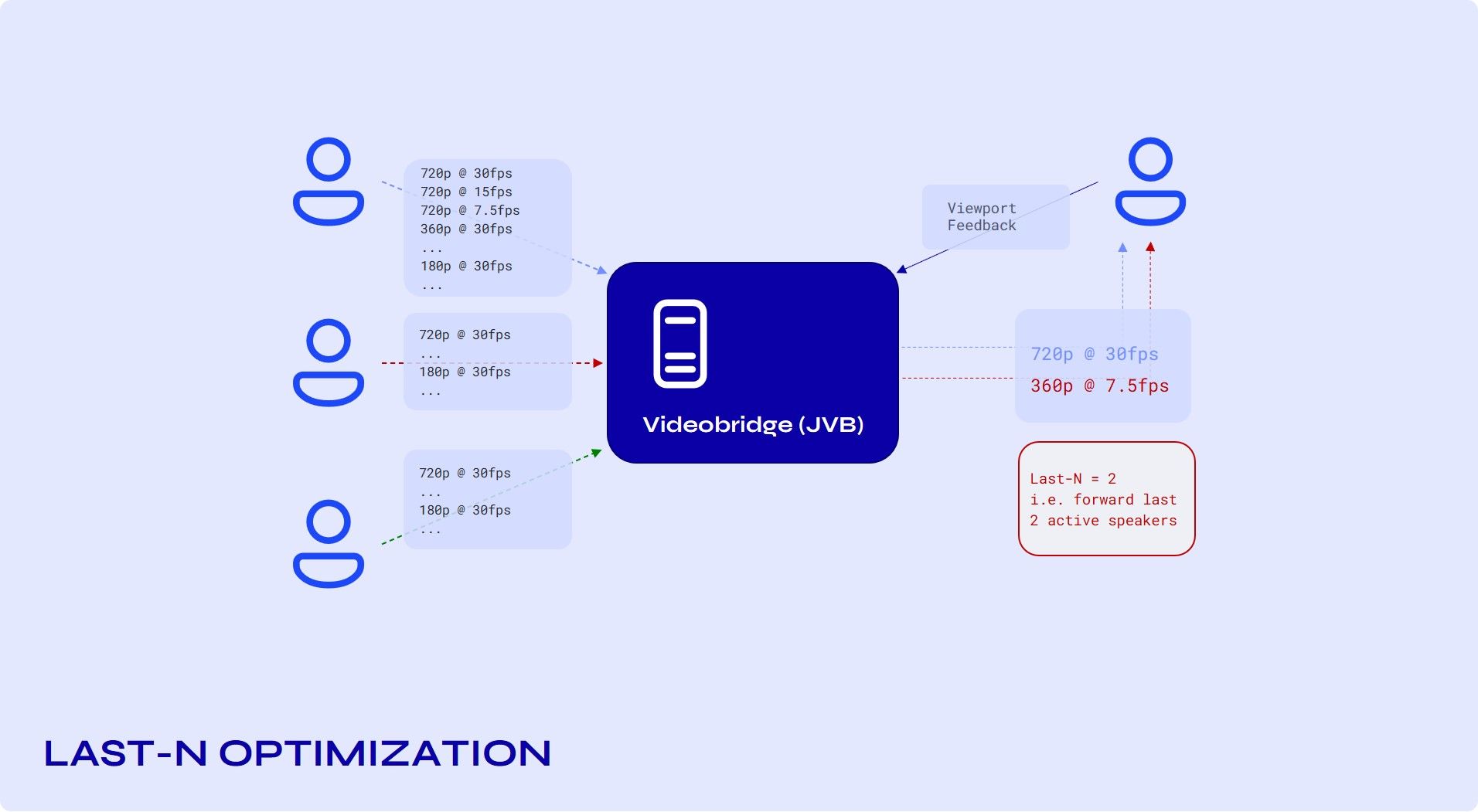
This approach greatly reduces the bandwidth consumed by the participants. Essentially, this limits the number of streams that everyone receives.
This means that in a conference with a hundred participants, rather than getting ninety-nine streams, everyone would only receive the streams for the last four, five, or N active speakers. This is what we call Last N, and it is something that really helps scalability.
Right now, N is a number that JVB deployments have as a config parameter, but we are working on making it adaptive so that JVB would adapt it based on link quality.
Off-Stage Layer Suppression
Simulcast trade off: As discussed above, simulcast is a great way to optimise download bandwidth. But, encoding 3 streams is more CPU intensive than, say, encoding one single stream. This is the tradeoff involved when using simulcast.
One way to further optimise and save on CPU costs is by suspending streams. Since we control the bridge, which controls the streams, it is possible to suspend streams being sent to the client which are not being viewed by them. By turning off the streams individually, simulcast gives us the opportunity to actually save both CPU and bits. If you’re not the active speaker, then 2 of your 3 layers aren’t needed at all!
P2P Mode
A user has the option to enable P2P mode, which is used (if enabled) when there are just 2 participants or coming 5G bandwidth; their numbers can increase up to 10-20, which will be great for cost optimization. One-to-one calls should avoid going through the JVB for optimal performance and optimal resource usage.
A direct connection is not always possible between the participants as UDP ports are blocked for some firewalls. In those cases, a TURN server is used to relay the traffic (JVB does much more than just relay the traffic, so this is not the same as using the JVB to "relay" the traffic).
Conclusion
In this post we have covered the architecture of our media server and the optimizations it offers.
Cost effectiveness and optimizations at the user’s end have been central to our development framework, and has allowed us to move past the legacy model of video delivery at all cost without any intelligence built into the infrastructure and delivery.
Building and integrating a webRTC compatible video conferencing solution limited to a few users is fairly simple. Configuring such a solution at global scale and optimizing for your end user gets very complex and time consuming. Sariska takes care of these complexities so that you can focus on your product and creative use cases, rather than spending time configuring and maintaining your communication infrastructure.
We are always keen on learning new engineering perspectives - whether you want to help re-engineer global communications, explore a use case or just have a chat - do get in touch with us directly on twitter/linkedin @sariskaio.
You can connect directly at @brajendra1221 and @dipakapid